As I said in the previous part, the wireless controller or basically the software do not worry me much as the mechanical mechanism. It turns out that rotating my door key is actually a difficult operation, but because I got leverage (large key), I didn't think so. My mechanical requirements are not simple as I thought also.
What are my requires?
1) The mechanism should not stick up too much from the door and should have sleek design. If its stick up more than the handle for example, it probably too much.
2) The actual key and cylinder should still be operational in case my controller fail to response.
3) The key should rotate in decent time (no more than few seconds)
I talked about my first design in the previous part, the motor/potentiometer/cylinder wrapped around a belt design. My assumption in this design is that the key can rotate the motor gear when idle, but this assumption is not correct, the gear is so strong that you can not rotate the key manually. Also, in this design I must use worm gear motors, because otherwise the motor profile is too high for my requirments, and worm gear motor cannot rotate at all in idle.
At this point I must reevaluate my further designs. If the motor is always connected, I won't be able to use the regular key because if I need strong motor with strong gear, I probably won't be able to turn it manually with decent amount of strength (and without breaking the key inside the cylinder). I must use some trigger that can disconnect the motor. The only mechanical trigger that can be applied from outside of the door is the door handle. I need to use the handle in order to connect/disconnect the motor in case of manual override by the key.
I tried using the worm gear concept in order to implement this attach/detach of the motor and also reduction in RPM in order to use regular motors without gears.


This is only the concept, the final design was much different. The screw and gear thread were more fine.
This design failed because the movement was so rough that it broke the motor axis. Maybe bearings will help that, but all of the parts should be super accurate in order for this design to work, but the handle is not really accurate and can move few mm freely.
In the next design I said no more! everything that can be moved should be held by a bearing, and I should handle each and every movement that the bearing does not.
The first part:
This part wrap around the cylinder and makes it 90 degress rotatable, I did this because I want to keep my profile low, and now I can use large motor without being too big.
The parts:
Bright Yellow - bearings
Purple - 45 degree bevel gears
All glued together
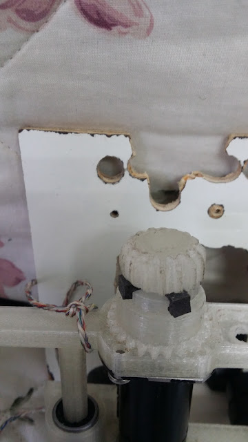
The light yellow is the "clutch", where the motor attach and detach depending on the handle:
The motor coupler is a spider coupler - two parts with rubber between them to make it flex.
The motor holder and linear bearing that sould connected to the handle.
adding screws and space for wires
The final testing design on the door
Google decided on his own to make this animation :O
The bottom line, this design somehow works! I can lock and unlock my door which is great. The testing is done on some ugly sheet of wood, I need to migrate all to nice aluminium, But at first I just wanted to check that everything is working.
Thanks for reading!


Hi These knowledge are very useful for us, you are very intelligent people and have shared good articles! We offer smart door lock, please visit our web site khoa cua dien tu samsung! thank you very much
ReplyDeleteThis comment has been removed by a blog administrator.
ReplyDelete